Precision voltage reference Circuit Diagram The downside to a voltage reference is that it only generates a single voltage and has limited current output. I decided to design a circuit that could generate any voltage between zero volts and 10 volts in 0.1 volt increments; for example, 4.8 volts with a basic accuracy of 10 millivolts and an output current of 100 milliamps (or one ampere This type of diode is widely found in the manufacture of voltage references from diodes to precision, for electronics circuits and systems needing a regulated output, such as in power supplies.
The following schematic depicts the poor man's precision voltage reference circuit (10.0V ±0.3%). The 1N5819 Schottky diode (D1) is placed along the power supply to avoid damaging the voltage reference chip should the power polarity be reversed. The RC low pass filter (R1-C1) is optional but it can scale down the noise from the power supply. The input voltage range is 12V to 36VDC.

Precision Voltage Reference Circuit Circuit Diagram
This video gives a step-by-step demonstration of an amplifier and precision reference based circuit design for a relatively inexpensive precision voltage source.

In this video, I have shared how you can build a precision voltage reference that can output 0 - 4995 mV with a resolution of 1mV.

Generating various reference voltages in a circuit Circuit Diagram
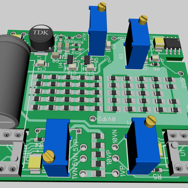
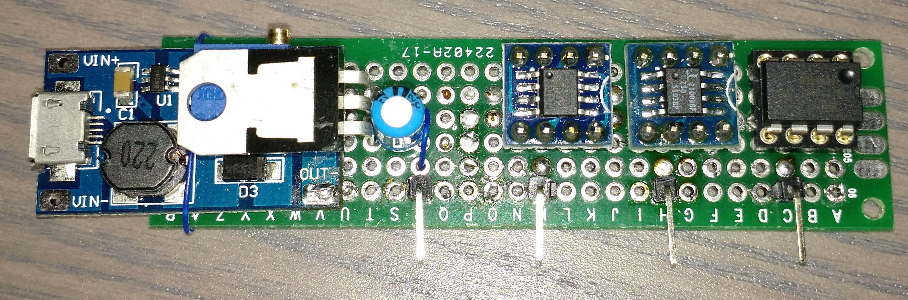
Phase 3: Build a professional proto The custom PCB version will be powered by battery as that will be desired. A boost converter for DAC voltage reference input and constant current circuit to work. I will also add isolated USB interface so that we can control the voltage current reference via PC. Display will be changed from OLED to a low power glass display which will consume 200-330uA while How does one go about accurately setting reference voltages at various points in a given circuit (e.g. various threshold voltages). Obviously we can have a potential divider from the main power supply but that generally tends to fluctuate a lot, not to mention noise from other parts of the circuit. I would assume a sort of single voltage reference from which we can derive the rest of the