

Voice Recognition System Circuit Diagram At its most basic level speech recognition allows the user
Category : Blog

PWM BASED DC MOTOR SPEED CONTROL DIY KIT Circuit Diagram
PWM BASED DC MOTOR SPEED CONTROL DIY KIT Circuit Diagram Motor control circuits are often
_oZdd8thver.png)
Smart Greenhouse Monitoring and controlling using iot Circuit Diagram
Smart Greenhouse Monitoring and controlling using iot Circuit Diagram The project's specific goals are to

How to make a Sound sensor using Condenser Mic Circuit Diagram
How to make a Sound sensor using Condenser Mic Circuit Diagram In today's video I

Design of a Li Circuit Diagram
Design of a Li Circuit Diagram Design and Implementation of Li-Fi System Sneha Jadhav, Suchit
Transmit Infrared Signals Through Walls Circuit Diagram
Transmit Infrared Signals Through Walls Circuit Diagram The IR Receiver The IR receiver used was
Use an LED matrix horizontally Circuit Diagram
Use an LED matrix horizontally Circuit Diagram Use the circuit figure below to connect the
monitoring Circuit Diagram
monitoring Circuit Diagram Therefore, it is needed to design an AI based Air Pollution Monitoring

Compare And Contrast Series Parallel Circuits Ppt Circuit Diagram
Compare And Contrast Series Parallel Circuits Ppt Circuit Diagram The components of the electrical DC
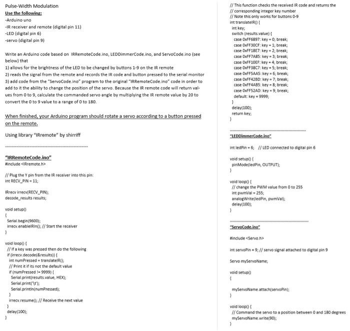
Pulsewidth Modulation Use the following Arduino Circuit Diagram
Pulsewidth Modulation Use the following Arduino Circuit Diagram Pulse-width modulation (PWM) can be implemented on

Try These Home Automation Ideas with Your Smart Doorbell Circuit Diagram
Try These Home Automation Ideas with Your Smart Doorbell Circuit Diagram Applications of the IoT
shooftie Circuit Diagram
shooftie Circuit Diagram Learn to read and understand any circuit diagram. There are only a
DIY Add WiFi to Normal Doorbell for Less Than 5 10 Steps Circuit Diagram
DIY Add WiFi to Normal Doorbell for Less Than 5 10 Steps Circuit Diagram JLCPCB
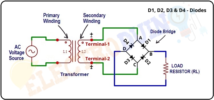
Full Wave Bridge Rectifier Circuit Diagram and Working Principle
Full Wave Bridge Rectifier Circuit Diagram and Working Principle Learn how to convert AC voltage

RFID entry monitoring system Hargreaves Asia Circuit Diagram
RFID entry monitoring system Hargreaves Asia Circuit Diagram Learn how to make Arduino RFID/NFC Door

sensing device with an MCU peripheral Circuit Diagram
sensing device with an MCU peripheral Circuit Diagram Figure 1-6. 8 mm Touch Sensor By

Houses Monitoring Consumption With Arduino UNO 4 Steps Circuit Diagram
Houses Monitoring Consumption With Arduino UNO 4 Steps Circuit Diagram Monitor your energy consumption through

Mua Electronic Devices and Circuit Theory trn Amazon M chnh hng Circuit Diagram
Mua Electronic Devices and Circuit Theory trn Amazon M chnh hng Circuit Diagram The following

Google Home Upgrades Automation Options for More Customization Circuit Diagram
Google Home Upgrades Automation Options for More Customization Circuit Diagram You can manually control the

Artificial Intelligence in Traffic Management Circuit Diagram
Artificial Intelligence in Traffic Management Circuit Diagram Here are some of the key ways in